CNC Pendant - Prototypes
Pendant to control my CNC mill with various G Code senders
Overview
This page is for the prototype pendants that I made along the way to building the 2020 Production model.
If you want to see the cutting edge in Hedge Court pendant technology, head over here.
It began with an interface to Universal G-Code Sender (UGS), starting out as a simple idea. Quickly grew into a fantastic exploration of design, construction, coding, and interface concepts. Many iterations, many proofs of concept, many do overs. Lots of fun, and lots of learning, exactly what I’m looking for in this hobby. As of this writing the Production 2020 model is in place on my X-Carve controlling my mill, bringing joy and efficiency to my manufacturing process.
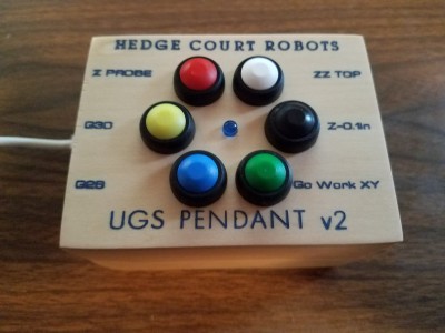
Prototype v2 - Simple and Compact
While this should logically be called “Prototype C”, I made and published a front panel saying “v2” so it is time to re-do the naming scheme. Maybe next one will be called “Prototype Llama”. Stick around to see.
After a short time in action, Prototype B stopped playing nice. I’m not sure if the number of resistors on that single pin causes some strange high impedance situation, or who really knows, but when it boots it runs pretty well, and over time (not very much time) it gets worse and worse, sometimes long delay to register button press, sometimes never. Additionally, even while working, it became a pain to remember to put the UGS mouse cursor in the command text box before operating the pendant. Design needs to change.
I decided to start over from the ground up:
- Arduino UNO replaces Pro Trinket. I want true USB and not the partial HID-emulator that is available with Pro Trinket.
- Java program running on the PC that will communicate with Arduino.
- Make use of the UGS Pendant UI, which allows http requests to send in GCode
- Scrap the button multiplexing for now. This iteration is to be a simple design with only a few buttons, each with a dedicated digital input on the Arduino. When I scale up to the final model I’ll have to figure out how to handle all those buttons, but for now, keep it simple.
Step one was to figure out the UGS Pendant UI. With the source code available, I quickly found the way to pass in arbitrary GCode. So now all I need is an httpClient that can respond to my button presses.
Enter the java application. On one side, it listens to the Arduino on USB. Arduino passes in a packed byte with some data about jog units (inches or mm), jog size (1.00, 0.10, 0.01), and a button index. The java application has a map of the button index to GCode. When a button press is received, it triggers an http client request to the Pendant web server, passing in the GCode.
Along the way I got myself into the fun world of open source contribution. The existing UGS code only allowed a single GCode command in a single request. For my Z Probe I have a series of commands that string together to perform the action, a macro if you will. So I got in the code for UGS, made my edits to loop on semicolon, and then worked with the project’s owner to get the changes integrated into the master branch of UGS to be included in future releases. Very interesting process to collaborate with total strangers on a coding project, and many kudos to the owner on organizing it all. Not an easy job.
For the physical construction, I used a 2x4 piece of wood and carved pockets big enough for switches and the arduino. This was a new concept for me and was very fun. The pockets were designed in Fusion 360 for some extra experience with that package. The front panel is made of basswood (very thin and brittle and soft, but what ever, this is a prototype). The layout was designed in Inkscape, then the holes were carved with Easel, the text was done with FEngrave. Of course, the first round had FEngrave reading the wrong origin, putting the text 5mm too far in Y axis. Flip it over and get it right. Oramask 813 provided a nice mask for painting, leaving pretty crisp lettering, even on the very soft and porous basswood. Sanding sealer before and after carving, two coats of acrylic paint, peel the mask, two layers of polyurethane. Beautiful.
My notes about the pocket for Prototype v2.
Prototype B - Point-to-Point Cardboard Box
After some initial success using Prototype A on my CNC, it was time to take the next step. The proto-A box was big and took up too much space on my workbench. The way the faceplate connected to the lid allowed for some movement when I pressed a button, which is a problem with solid core wires connected to a solderless breadboard. Further, with solderless breadboard you have feeble connections that come loose when you accidentally drop the box (not that I would do such a clumsy thing, right?).
I spent some time debating the next step for Prototype B. My heart wanted to carve a PCB for the circuit using my CNC. I downloaded and learned basic Eagle CAD usage, and then built the schematic and PCB board layout. Then some experimentation with Chilipeppr to carve the board. Ended up deciding to scrap this, there are just too many moving parts, I need to take baby steps here. Plus, when I (didn’t) drop the box and my X- jog button came loose, I figured an interim solution was needed.
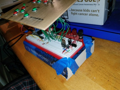
I hate rats nest point-to-point wiring, but that’s exactly what I went for. There are only a few connections in this circuit, mainly a ton of connections to GND and Test Point 1 busses. Slowly, carefully, patiently, I made the rats nest. Plugged it in, frowny face because it didn’t work. Then I remembered there’s an issue with whether I use the USB connection for operation or the FTDI friend connector, so switched it out and worked nicely.
Found a suitably sized box and made a much more tidy, solid, secure enclosure and attachment. And Prototype B is in action!
Next Steps
Next step….possibly build a wooden enclosure using the CNC to replace the cardboard box. Or I might just move on to some other carving projects now that I have a more reliable pendant, even if it is in a cardboard box.
Prototype A - Solderless Cardboard Box
The technical concepts behind this project are pretty simple. Read a push button, emulate some keyboard key presses, illuminate a few LED indicators to display some states. Very easy to prototype on a solderless breadboard.
Analog Push Buttons
A special consideration with this project is the sheer number of buttons I’d like to use. If I were to dedicate a digital input pin for each input, I’d be up the creek pretty fast. Since I am not interested in concurrent button presses (i.e. only one button will be pressed at any point in time), I can use a single input pin for 10 or more buttons. Build a voltage divider with a single static resistor tied to Vcc on one side and a test point on the other. Connect an ADC pin to this test point. Then connect each push button to the test point on one side, and to a unique resistor value on the other side. Finally, connect the resistors to ground to complete the circuit.
As long as (A) only one button at a time gets pressed and (B) unique resistor values chosen across a wide spred of values, then you get a nice clean zone of ADC readings that matches each push button. Very easy to prototype this on the solderless breadboard. Prove the concept with two buttons, and then easily scale up, adding new button/resistor pairs. Very quickly got 10 buttons on a single pin, with plenty of “ADC range” left for 4-5 more buttons is needed.
Face Plate
Man, I wish I took a pic before I built the face plate because I had all of the pushbuttons sticking up out of a solderless breadboard on rigid solid core wires with green insulator, looking like sea kelp growing up from the ocean floor. But that was a mess, had no way to know what button was what feature, was feeble, and prone to short circuits. I needed a face plate.
This is where lots and lots of CNC milling education came in. Just a simple 2.5d panel requires quite a bit of thought. The biggest issue I ran into was the hole sizes. I laid the whole design out in Inkscape, setting the hole sizes to match my buttons. Easel can import the .svg file from Inkscape and create the G-Code. Run this G-Code through UGS, have the X-Carve cut the holes and engrave the text, and get a front plate. Go push an LED into what is supposed to be a 5mm hole and NO JOY. Hole way too small.
Lots of CNC mill calibration followed. Belt tensions. Stepper motor steps per mm calculations and calibrations in all three axis. Bit measurement and calibration for various hole sizes in the desired wood type. Tons of research, tons of learning, tons of scrap wood for the pile. Finally achieved proper sizes.
On to wood finishing. Sanding with various reducing grit papers. Shellac coats. Paint coats. Shellac top coats. Learned that this specific paint is NOT a good option under shellac. The paint dissolved and ran, making my letters appear like Alice Cooper’s eye makeup. I have other paints that work fine under shellac so final product will not have this feature.
Enclosure
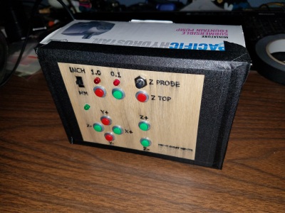
Amazon Prime is a great shopping/delivery service. It also leaves you with an endless supply of prototype electronic project enclosures, aka cardboard boxes. I pretty much just cut a hole in the top of a box, carefully positioned the solderless breadboard in the bottom (stealing one of my wife’s books from her DONE pile to prop up the bottom and fill some space), and taped the face plate over the hole. I ran two cables out of the box: USB to serve as HID keyboard connection to host computer in execution mode, and FTDI to upload new firmware/sketches to the controller in programming mode.
It’s Alive
Using just a single, very safe G-Code command, I was ready to test it out. Step 1, test the keyboard output in a simple text editor on the target host computer. Success. Step 2, test the output in a live situation connected to the CNC machine.
Connect UGS to my GRBL controller, position the mous cursor in the UGS command window text input box, ensure all children and animals are a safe distance away. Press the button…NAILED IT! G-Code output is exactly what I wanted. The machine responded with the desired physical movement. Time to build the real firmware.
Overall Function
There are three types of buttons on the system: state modifiers, jog commands, and macros.
The state modifiers are for the user to select certain states. No key presses are sent to the host computer in response to these. Instead, these are used to modify the output that is sent for other presses. One button is a SPST switch to toggle the units between inches and millimeters. The other two buttons select the unit size, either 1.0 or 0.1. Inch/MM has no LED indicator because it is visibly clear what position the switch is in. The unit size has an LED indicator to show the user which size is selected. With only two sizes to select, I could have uses a switch just like the inch/mm selector. The production model is planned to have a third choice for 0.01, so I thought it looked nice to do it this way.
The JOG buttons send real G-Code output to the USB host, as though a human operator had typed them directly via keyboard. The function that runs for the 6 JOG buttons makes use of the modifiers when assembling the G-Code to send, ensuring proper units (inches/mm), jog size (1.00/0.10/0.01), proper axis (X/Y/Z), and proper direction (+/-).
The MACRO buttons send static strings of G-Code that I hardcode in the program. In this case I have a long string of G-Code for a double-tap height probing in the Z-axis, and a specific setting in absolute machine coordinates for my top Z position, allowing me to quickly raise the bit up for work inspections or bit changes. I expect the final production model will have a few more of these, after I play with CNC machining for a bit and learn what I want.
It felt weird that there was no visual cue I had pressed a button. So I improvised a quick solution, and manually drilled a 5mm hole for the green LED. A small modification to the firmware and it glows the green LED for a short duration (.3 sec) after I press a JOG or MACRO.
The text in the lower right was a test of font size and painting. I used a very small font and used the basic Easel software to engrave it. The plain letters came out good enough. The paint (applied with a tooth pick) is only slightly good looking. Need to try again with F-Engrave to see if higher quality on tiny letters can be achieved.


